Design Documentation
So you’d like a technical overview of how The Overviewer works, huh? You’ve come to the right place!
This document’s scope does not cover the details of the code. The code is fairly well commented and not difficult to understand. Instead, this document is intended to give an explanation to how the Overviewer was designed, why certain decisions were made, and how all the pieces fit together. Think of this document as commenting on how all the high level pieces of the code work.
This document is probably a good read to anyone that wants to get involved in Overviewer development.
So let’s get started!
Note
This page is continually under construction.
Contents
Background Info
The Overviewer’s task is to take Minecraft worlds and render them into a set of tiles that can be displayed with a Leaflet interface. This section goes over how Minecraft worlds work and are stored.
A Minecraft world extends indefinitely along the two horizontal axes, and are exactly 256 units high. Minecraft worlds are made of voxels (volumetric pixels), hereby called “blocks”, where each block in the world’s grid has a type that determines what it is (grass, stone, …). This makes worlds relatively uncomplicated to render, the Overviewer simply determines what blocks to draw and where. Since everything in Minecraft is aligned to a strict grid, placement and rendering decisions are completely deterministic and can be performed iteratively.
The coordinate system for Minecraft has three axes. The X and Z axes are the horizontal axes. They extend indefinitely towards both positive and negative infinity. (There are practical limits, but no theoretical limits). The Y axis extends from 0 to 255, which corresponds with the world height limit. Each block in Minecraft has a coordinate address, e.g. the block at 15,78,-35 refers to 15 along the X axis, -35 along the Z axis, and 78 units up from bedrock.
The world is organized in a three-layer hierarchy. At the finest level are the blocks (voxels). A 16x16x16 array of blocks is called a chunk section. A vertical column of 16 chunk sections makes a chunk. A chunk is therefore a 16 by 16 area of the world that extends from bedrock to sky. In other words, a 16 by 256 by 16 “chunk” of the world. A 32 by 32 area of chunks is called a region. Regions are stored on disk one per file.
While blocks have a global coordinate (the ones you see in the debug output in-game), they also have a local coordinate within a chunk section and within a chunk. Also, chunks and regions have their own coordinates to identify themselves. To find which chunk a block is in, simply divide its coordinates by 16 and take the floor. To find which region a chunk is in, divide the chunk coordinates by 32 and take the floor. To find which chunk section a block is in, take its Y coordinate and floor-divide by 16.
Minecraft worlds are generated on-the-fly by the chunk. This means not all chunks will exist, and not all sections within a chunk will exist. There is no pattern to which chunks are generated, the game generates them as needed as players explore the area. A region file may not exist if none of its chunks exist.
Overviewer at a High Level
Minecraft worlds are rendered in an approximated Isometric projection at an oblique angle. In the original design, the projection acts as if your eye is infinitely far away looking down at the world at a 45 degree angle in the South-East direction (now, the world can be rendered at any of the 4 oblique directions).
The Overviewer is a sprite-based renderer. Each block type corresponds to a pre-rendered sprite (a small image). The basic idea is to iterate over the blocks of the world and draw these sprites to the appropriate location on the map.
These are the high-level tasks The Overviewer must perform in rendering a map:
- Render each block sprite from the textures
- Scan the chunks of the world and determine which tiles need rendering
- Render a chunk by drawing the appropriate blocks sprites on an image
- Render a tile of the map from several chunk images
- Compose the lower-zoom tiles from the higher-zoom tiles
The next sections will go over how these tasks work.
Block Rendering
The first step is rendering the block sprites from the textures. Each block is
“built” from its textures into an image of a cube and cached in a
Textures object.
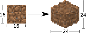
Textures come from files inside of a “textures” folder. If the file is square (has equal width and height dimensions), it is scaled down to 16 x 16 pixels. Non-square images are used with animated textures. In this case, the first frame of the animated texture is used, and also scaled to a 16 by 16 image. In order to draw a cube out of the textures, an affine transformation is applied to the images for the top and sides of the cube in order to transform it to the appropriate perspective.
Note
This section goes over the simple case for a regular cube, which are most of
the blocks in Minecraft. There are lots of irregular blocks that aren’t
cubes (fences, torches, doors) which require custom rendering. Irregular
blocks are not covered by this design document. Each type of block has its
own function in overviewer_core.textures that defines how to render
it.
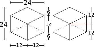
Every block sprite is exactly 24 by 24 pixels in size. This particular size for the cubes was chosen for an important reason: 24 is divisible by 2 and by 4. This makes placement much easier. E.g. in order to draw two cubes that are next to each other in the world, one is drawn exactly 12 pixels over and 6 pixels down from the other. All placements of the cubes happen on exact pixel boundaries and no further resolution is lost beyond the initial transformations. (This advantage will become clear in the Block Positioning section; all offsets are a nice even 6, 12, or 24 pixels)
A cube sprite is built in two stages. First, the texture is transformed for the top of the cube. Then the texture is transformed for the left side of the cube, which is mirrored for the right side of the cube.
Top Transformation
The transformation for the top face of the cube is a simple affine transformation from the original square texture. It is actually several affine transformations: a re-size, a rotation, and a scaling; but since multiple affine transformations can be chained together simply by multiplying the transformation matrices together, only one transformation is actually done.
This can be seen in the function
overviewer_core.textures.transform_image(). It performs three steps:
- The texture is re-sized to 17 by 17 pixels. This is done because the diagonal of a square with sides 17 is approximately 24, which is the target size for the bounding box of the cube image. So when it’s rotated, it will be the correct width. (Better to scale it now than after we rotate it)
- The image is rotated 45 degrees about its center.
- The image is scaled on the vertical axis by a factor of 1/2.
This produces an image of size 24 by 12 as seen in the following sequence.
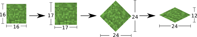
The final image, shown below, becomes the top of the cube.

On the left is what will become the top of the block at actual size after the transformation, the right is the same but blown up by a factor of 10 with no interpolation to show the pixels.
Side Transformation
The texture square is transformed for the sides of the cube in the
textures.transform_image_side() function. This is another affine
transformation, but this time only two transformations are done: a re-size and
a shear.
- First the texture is re-sized to 12 by 12 pixels. This is half the width of 24 so it will have the correct width after the shear.
- The 12 by 12 square is sheared by a factor of 1.5 in the Y direction, producing an image that is bounded by a 12 by 18 pixel square.
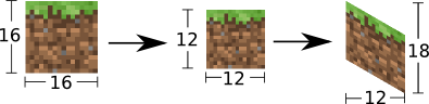
This image is simply flipped along the horizontal axis for the other visible side of the cube.
Again, shown on the left are the two sides of the block at actual size, the right is scaled with no interpolation by a factor of 10 to show the pixels.
An Entire Cube
These three images, the top and two sides, are pasted into a single 24 by 24 pixel image to get the cube sprite, as shown.
However, notice from the middle of the three images in the sequence below that the images as transformed don’t fit together exactly. There is some overlap when put in the 24 by 24 box in which they must fit.
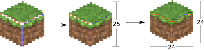
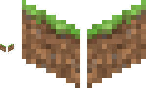
There is one more complication. The cubes don’t tessellate perfectly. A six pixel gap is left between the lower-right border and upper-left border of blocks in this arrangement:
The solution is to manually touch up those 6 pixels. 3 pixels are added on the upper left of each cube, 3 on the lower right. Therefore, they all line up perfectly!
This is done at the end of Textures.build_block()
Chunk Rendering
With these cube sprites, we can draw them together to start constructing the world. The renderer renders a single chunk section (a 16 by 16 by 16 group of blocks) at a time.
This section of the design doc goes over how to draw the cube sprites together to draw an entire chunk section.
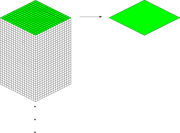
How big is a chunk section going to be? A chunk section is a cube of 16x16x16 blocks.
Rendered at the appropriate perspective, we’ll have a cube made up of 4096 smaller cubes, like this:
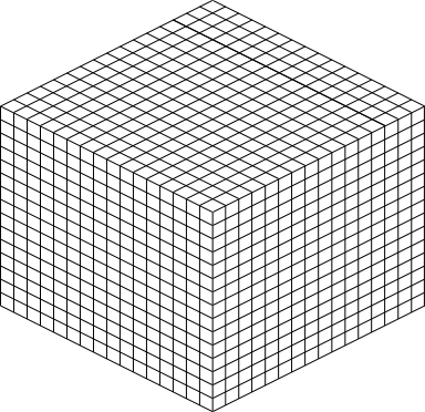
Each of those cubes shown is where one of the pre-rendered block sprites gets pasted; the entire thing is a chunk section. The renderer iterates over a chunk layer-at-a-time from bottom to top, drawing the sprites. The order is important so that the it gets drawn correctly. Obviously if a sprite in the back is pasted on the image after the sprites in the front are drawn, it will be drawn on top of everything instead of behind.
Block Positioning
A single block is a 24 by 24 pixel image. Before we can construct a chunk section out of individual blocks, we must figure out how to position neighboring blocks.
First, to review, these are the measurements of a block sprite:
- The image is bounded by a 24 by 24 pixel square.
- The side vertical edges are 12 pixels high.
- The top (and bottom) face of the block takes 12 vertical pixels (and 24 horizontal pixels).
- The edges of the top and bottom of the block take up 6 vertical pixels and 12 horizontal pixels each.
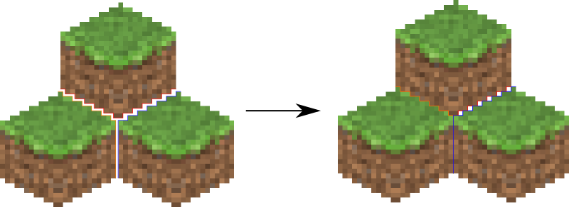
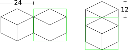
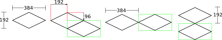
Two blocks that are neighbors after projection to the image (diagonally neighboring in the world) have a horizontal offset of 24 pixels from each other, as shown below on the left. This is mostly trivial, since the images don’t overlap at all. Two blocks in the same configuration but rotated 90 degrees have some overlap as shown on the right, and are only vertically offset by 12 pixels.
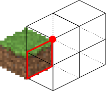
Now for something slightly less intuitive: two blocks that are stacked on top of each other in the world. One is rendered lower on the vertical axis of the image, but by how much?
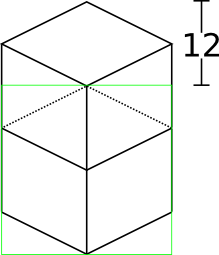
Interestingly enough, due to the projection, this is exactly the same offset as the situation above for diagonally neighboring blocks. The block outlined in green is drawn 12 pixels below the other one. Only the order that the blocks are drawn is different.
And finally, what about blocks that are next to each other in the world — diagonally next to each other in the image?
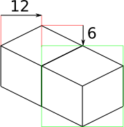
The block outlined in green is offset on the horizontal axis by half the block width, or 12 pixels. It is offset on the vertical axis by half the height of the block’s top, or 6 pixels. For the other 3 directions this could go, the directions of the offsets are changed, but the amounts are the same.
The size of a chunk
Now that we know how to place blocks relative to each other, we can begin to construct an entire chunk section.
Since the block sprites are 24 by 24 pixels, and the diagonal of the 16 by 16 grid is 16 squares, the width of one rendered chunk section will be 384 pixels. Just considering the top layer of blocks within a section:
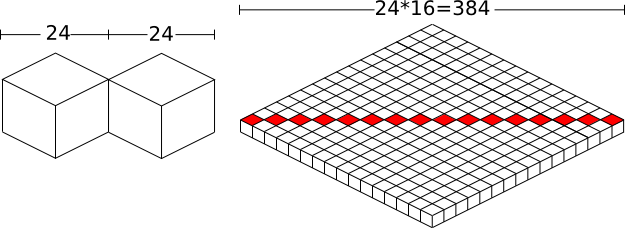
Since blocks next to each other in the same “diagonal row” are offset by 24 pixels, this is trivially calculated.
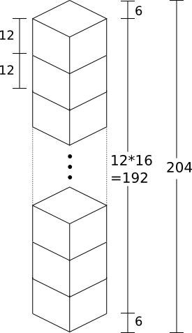
The height is a bit more tricky to calculate. Let’s start by calculating the height of a single stack of 16 blocks.
The non-overlapping edge of each block sprite is 12 pixels high. Since there are 16 blocks in this stack, that’s 192 pixels high. There are also 6 additional pixels at the top and bottom of the stack as shown, giving a total height of 204 pixels.
But that’s just for one column of blocks. What about the entire chunk section? Take a look at this diagram:
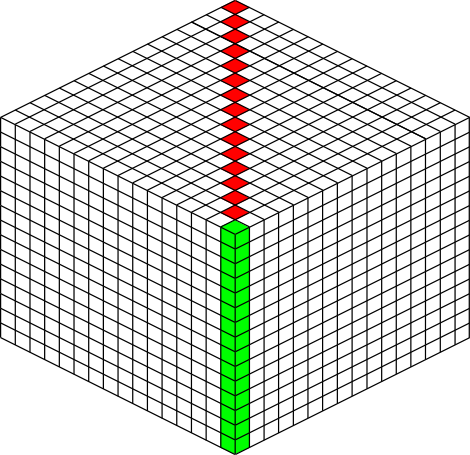
The green highlighted blocks are the stack we calculated just above and have a height of 204 pixels. The red highlighted blocks each take 12 pixels of vertical space on the image, and there are 15 of them. So 204 + 12*15 is 384 pixels.
So the total size of a chunk section in pixels is 384 wide by 384 tall.
Assembling a Chunk
Now that we know how to place blocks, here’s how they are arranged to form an entire chunk section. The coordinate system is arranged as shown, with the origin being at the left corner.

To ensure that block closer to the viewer are drawn on top while blocks that should be obstructed are drawn are hidden, the blocks are drawn one layer at a time from bottom to top (Y=0 to Y=15) and from back to front.
From the data file on disk, block information in a chunk is a three-dimensional array of bytes, each representing a block id. The process of assembling a chunk is simply a matter of iterating over this array, reading the blockid values, looking up the appropriate sprite, and pasting it on the chunk image at the appropriate location.
Chunk Placement
Now that we know how to draw a single chunk, let’s move on to how to place chunks relative to each other.
Before we get started, let’s take a moment to remember that one chunk section is only 1/16th of a chunk:
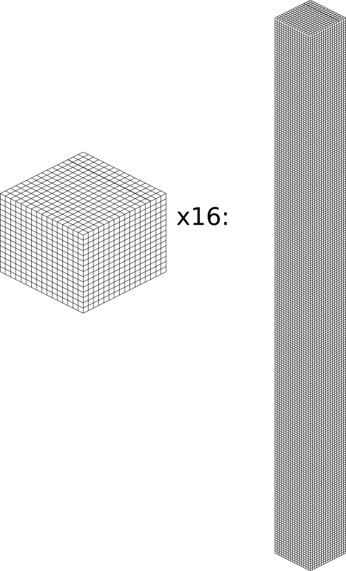
A chunk is 16 chunk sections stacked together.
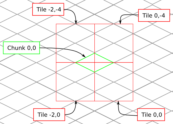
Since this is pretty tall, the diagrams in this section are simplified to only show the top face of a chunk, as shown in green here:
This makes it easier and less cumbersome to describe how to place chunks together on a tile. Just remember that chunks are actually very tall and extend down far beyond the drawn diamonds in these diagrams.
Chunk Addressing
Chunks in Minecraft have an X,Z address, with the origin at 0,0 and extending to positive and negative infinity on both axes (Recall from the introduction that chunk addresses are simply the block addresses divided by 16). Since we’re going to render at a diagonal perspective, it is convenient to perform a change of coordinate system. For that, we translate X,Z coordinates into column,row coordinates. Consider this grid showing 25 chunks around the origin. They are labeled with their X,Z chunk addresses.

Now, we want to transform each chunk to a row/column address as shown here:
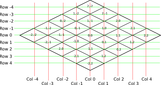
So the chunk at address 0,0 would be at col 0, row 0; while the chunk at address 1,1 would be at col 2, row 0. The intersection of the red and green lines addresses the chunk in col,row format.
Note
As a consequence of this addressing scheme, there is no chunk at e.g. column 1 row 0. There are some col,row addresses that lie between chunks, and therefore do not correspond to a chunk. (as can be seen where the red/green lines intersect at a chunk boundary instead of the middle of a chunk).
So how does one translate between them? It turns out that a chunk’s column address is simply the sum of the X and the Z coordinate, while the row is the difference. Try it!
col = X + Z
row = Z - X

X = (col - row) / 2
Z = (col + row) / 2
Chunk Positioning
This section will seem very familiar to the block positioning. In fact, it is exactly the same but with different numbers (because blocks and chunk sections have the exact same proportions), so let’s speed through this.
A chunk’s top face is 384 pixels wide by 192 pixels tall. They therefore have these offsets from their neighbors:
Tile Rendering
Now that we know how to translate chunk coordinates to col/row coordinates, and know how to calculate the offset from the origin on the final image, we could easily draw the chunks in one large image. However, for large worlds, that would quickly become too much data to handle at once. (Early versions of the Overviewer did this, but the large, unwieldy images quickly motivated the development of rendering to individual tiles).
Hence choosing a technology like Google Maps or Leaflet, which draws small tiles together to make it look like one large image, lets rendering even the largest worlds possible. The Overviewer can draw each tile separately and not have to load the entire map into memory at once. The next sections describe how to determine which chunks to render in which tiles, and how to reason about tile ↔ chunk mappings.
Tile Layout
Instead of rendering to one large image, chunks are rendered to small tiles. Only a handful of chunks need to be rendered into each tile. The downside is that chunks must be rendered multiple times for each tile they appear in, but the upside is that arbitrarily sized maps can be viewed.
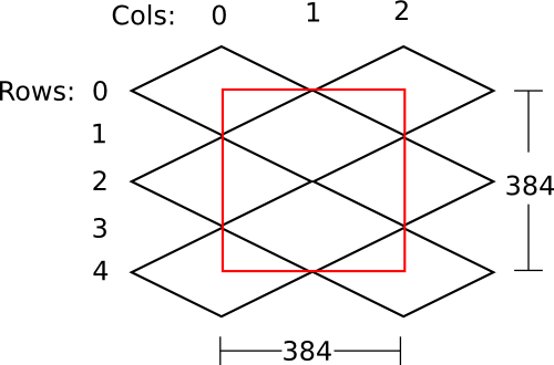
The Overviewer uses a tile size of 384 by 384 pixels. This is the same as the size of a chunk section and is no coincidence. Just considering the top face of a chunk, the 8 chunks directly below it get rendered into a tile in this configuration:
Note
Don’t forget that chunks are tall, so many more than 8 chunks get rendered into this tile. If you think about it, chunks from the rows above the ones in that diagram may have blocks that fall into this tile, since the diamonds in the diagram correspond to the tops of the chunks, and chunks extend down.
Note
This is an important diagram and we’ll be coming back to it. Make sure it makes sense. As a side note, if anything in this document doesn’t make sense, please let us know in IRC or by filing an issue. I want these docs to be as clear as possible!
So the overall strategy is to convert all chunks into diagonal col,row coordinates, then for each tile decide which chunks belong in it, then render them in the appropriate place on the tile.
The rendering routines are actually passed a range of chunks to render, e.g. rows 4-6, cols 20-24. The lower bound col,row chunk given in the range is rendered at position 0,0 in the diagram above. That is, at offset -192,-96 pixels.
The rendering routines takes the given range of columns and rows, converts it back into chunk coordinates, and renders the given 8 chunks plus all chunks from the 16 rows above the given range (see the note below). The chunks are positioned correctly with the above positioning rules, so any chunks that are out of the bounds get rendered off the tile and don’t affect the final image. (There is therefore no penalty for rendering out-of-bounds chunks for a tile except increased processing)
Since every other column of chunks is half-way in two tiles, they must be rendered twice. Each neighboring tile is therefore only 2 columns over, not 3 as one may suspect at first. Same goes for the rows: The next tile down is 4 rows down, not 5.
To further illustrate this point, here are four tiles arranged on the grid of chunks. Notice how the tiles are addressed by the col,row of the chunk in the upper-left corner. Also notice how neighboring tiles are 2 columns apart but 4 rows apart.
Quadtrees
Tiles are rendered and stored in a quadtree on disk. Each node is a tile of the world, and each node has four children representing a zoomed-in tile of the four quadrants.
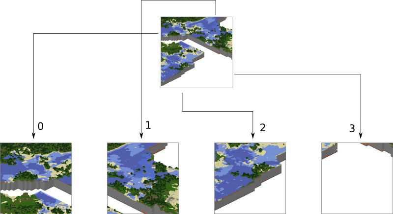
The tree is generated from the bottom-up. The highest zoom level is rendered directly from the chunks and the blocks, then four of those rendered tiles are shrunk and concatenated to get the next zoom level. The tree is built up in this way until the entire world is compressed down to a single tile.
We’ve already seen how tiles can be identified by the column,row range of the chunks that make up the tile. More precisely, since tiles are always the same size, the chunk that goes in the tile’s 0,0 col,row slot identifies the tile.
Now, tiles are also identified by their path in the quadtree. For example,
3/0/0/1/1/2.png refers to the tile starting at the base, under the third
quadrant, then the 0th quadrant, then the 0th, and so fourth.
Quadtree Size
The size of the quadtree must be known before it’s generated, that way the code knows where to save the images. This is easily calculated from a few realizations. Each depth in the quadtree doubles the number of tiles in each dimension, or, quadruples the total tiles. While there is only one tile at level 0, there are four at level 1, 16 at level 2, and 4^n at level n.
To find how deep the quadtree must be, we look at the size of the world. First find the maximum and minimum row and column of the chunks. Just looking at columns, let’s say the maximum column is 82 and the minimum column is -136. A zoom level of 6 will be 2^6 tile across and 2^6 tiles high at the highest level.
Since horizontally tiles are two chunks wide, multiply 2^6 by 2 to get the total diameter of this map in chunks: 2*2^6. Is this wide enough for our map?
It turns out it isn’t (2*2^6=128, 136+82=218). A zoom level of 7 is 2^7 tiles across, or 2*2^7 chunks across. This turns out is wide enough (2*2^7 = 256), however, Overviewer maps are always centered at point 0,0 in the world. This is so tiles will always line up no mater how the map may expand in the future.
So zoom level 7 is not enough because, while the chunk diameter is wide enough, it only extends half that far from the origin. The chunk radius is 2^7 (half the diameter) and 2^7=128 is not wide enough for the minimum column at absolute position 136.
So this example requires zoom level 8 (at least in the horizontal direction. The vertical direction must also be checked).
Quadtree Paths
To illustrate the relationship between tile col,row addresses and their path, consider these 16 tiles from a depth 2 quadtree:
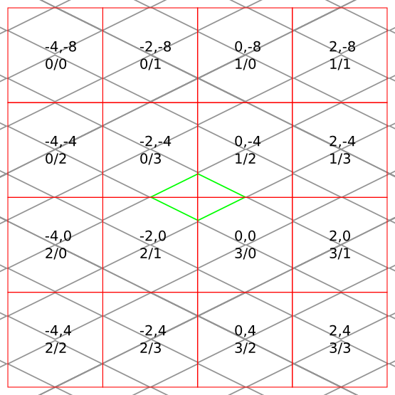
The top address in each tile is the col,row address, where the chunk outlined in green in the center is at 0,0. The lower address in each tile is the path. The first number indicates which quadrant the tile is in overall, and the second is which quadrant within the first one.
Lighting
Minecraft stores precomputed lighting information in the chunk files
themselves, so rendering shadows on the map is a simple matter of
interpreting this data, then adding a few extra steps to the render
process. These few extra steps may be found in
rendermode-lighting.c or rendermode-smooth-lighting.c,
depending on the exact method used.
Each chunk contains two lighting arrays, each of which contains one value between 0 and 15 for each block. These two arrays are the BlockLight array, containing light received from other blocks, and the SkyLight array, containing light received from the sky. Storing these two seperately makes it easier to switch between daytime and nighttime. To turn these two values into one value between 0 and 1 representing how much light there is in a block, we use the following equation (where lb and ls are the block light and sky light values, respectively):

For night lighting, the sky light values are shifted down by 11 before this lighting coefficient is calculated.
Each block of light data applies to all the block faces that touch it. So, each solid block doesn’t receive lighting from the block it’s in, but from the three blocks it touches above, to the left, and to the right. For transparent blocks with potentially strange shapes, lighting is approximated by using the local block lighting on the entire image.
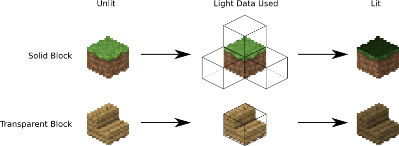
For some blocks, notably half-steps and stairs, Minecraft doesn’t generate valid lighting data in the local block like it does for all other transparent blocks. In these cases, the lighting data is estimated by averaging data from nearby blocks. This is not an ideal solution, but it produces acceptable results in almost all cases.
Smooth Lighting
In the smooth-lighting rendermode, solid blocks are lit per-vertex instead of per-face. This is done by covering all three faces with a quadralateral where each corner has a lighting value associated with it. These lighting values are then smoothly interpolated across the entire face.
To calculate these values on each corner, we look at lighting data in the 8 blocks surrounding the corner, and ignore the 4 blocks behind the face the corner belongs to. We then calculate the lighting coefficient for all 4 remaining blocks as normal, and average them to obtain the coefficient for the corner. This is repeated for all 4 corners on a given face, and for all visible faces.
The ambient occlusion effect so strongly associated with smooth lighting in-game is a side effect of this method. Since solid blocks have both light values set to 0, the lighting coefficient is very close to 0. For vertices in corners, at least 1 (or more) of the 4 averaged lighting values is therefore 0, dragging the average down, and creating the “dark corners” effect.